
However, a pull-up resistor improves the pin's driving ability. This situation affects the regular operation of the entire microcontroller board system. Peripheral circuits have a minor influence on the digital course if the output is high because it does not attain a V CC state. To Increase The Output Pin's Load Capacity This malfunction is due to the microcontroller's pin-level remaining uncertain at the power-on moment. These include: To Avoid Malfunctions by Improving Circuit StabilityĪ digital logic circuit can malfunction when you press the switch's button if the resistor does not pull it up to a high level.

Pull-up and pull-down resistors have two functions. V PIN = V DD x R IMPEDANCE / (R PULL UP + R IMPEDANCE) The Functions of the Pull-up Resistor and Pull-down Resistor Since V DD is the input/supply voltage in the pull-up circuit and the output voltage is the voltage at the input signal pin, the formula becomes: Using the voltage divider formula, you can calculate the input pin voltage with the button not pushed using the following.

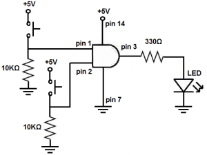
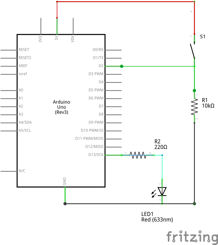
The grounded resistor forms the input pin impedance, and when combined, the two make up a voltage divider.Ī pull-up resistor connection to a digital chipĬomparing it to a standard voltage divider, the pull-up resistor in this circuit is equivalent to R1, while the input impedance is R2. Think of an ICs input signal pin connected to the V DD (circuit's positive supply voltage) via a resistor and another resistor connecting this input to the ground. Pull up and pull down resistors ensure the circuitry delivers the expected switching condition by pulling the input signal to a known state. If there is no input condition on the gates, correct biasing prevents random floating.ĭigital logic gates usually contain multiple input and output pins, and these need a correct setting (low or high) for the digital circuit to work as required. In a nutshell, pull-up and pull-down resistors are critical components used to bias the inputs of digital gates, micro-controllers, and ICs correctly. What are Pull Up and Pull Down Resistors? Such a form of control is critical in digital devices, and we will take a closer look at these two components to differentiate them and see how they work. It reduces the voltage flowing into the digital device.

A resistor's primary function is to reduce current flow, but it can also serve as a voltage divider. The components that can help you achieve this bias are pull-up and pull-down resistors. Therefore, for such devices to deliver the expected condition, their inputs must have the right setting or bias. Digital devices, logic gates, microcontrollers, and the like have specific logic voltages that determine whether the input is a logic high (1) or a logic low (0).


 0 kommentar(er)
